Some Images and a couple of new observations.
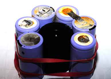
Battery Pack and former. Watch that you build the pack the 'right' way around or you will end up with the +ve and -ve terminals swapped - this will not be funny.
Yea, this is my 'old' pack that got a bit wet, the new one was built and fitted before I took the picture.
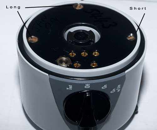
Built pack - showing location of long and short screws
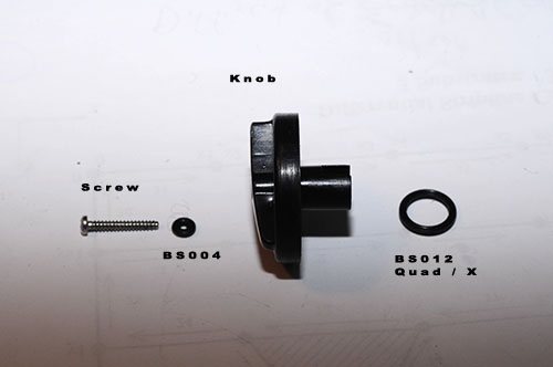
Knob build - this is one of the finest pieces of design stupidity I have encountered for a while.
While thinking about it in the bath last night I decided that there had to be another O-Ring involved in the switch assembly.
Well here it is, BS004, under the head of the screw. Put it in dry, do not lube as it may extrude when the screw is tightened up.
I may fill behind the screw head with RTV as I can't say I trust this much at all.
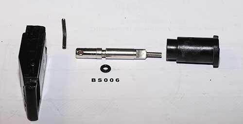
This is the one that I sheered off and broke. Drilled and tapped M3, put in a M3 stub.
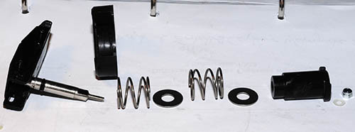
Build order for springs and shaft, I have left the battery case out of the shot for clarity. Essentially the battery case comes between the LHS spring and the black plastic piece that controls the 90 deg of rotation.
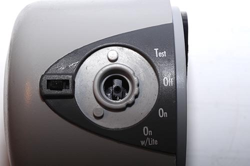
The PCB is not properly aligned yet in this shot - move it with a screwdriver then put the knob in place, I found the best way was to fit the quad ring to the knob before inserting it into the body.
The screws are not yet fitted which is why the back plate is at a wonky angle.
Be careful how the screw is tightened - not enough it will leak - too much you will strip the thread out or extrude the O-Ring bodge that is going on underneath.
If anyone needs the quad rings I have just ordered some spares for myself (I ordered 10).
Paul C







